NeXT CDROM Restoration

If your CDROM drive spins up but never can read disks or is immediately ejected, you likely have leaking capacitors.

Drive Description

The NeXT CDROM is a rebranded Sony SCSI 1X CD drive (CDU-541-01). This drive was rebranded by other contemporary vendors as well. The following drives will contain similiar parts:

Vendor
Model
SONY Part #
ROM
Enclosure
Notes
Apple
AppleCD 150
CDU-541-25
APL 1.8g 1289
SONY, White
White faceplate, Board level incompatible with NeXT ROM
Apple
AppleCD SC Plus
CDU-541-22 APL-1.8d FEGA
Custom, White
White faceplate, Custom Apple Enclosure, Board level compatible with NeXT ROM
DEC
RRD42-AA
RRD42-AA
DEC 4.5d EEC3
SONY, Grey
Grey faceplate, 100% Hardware Match. NeXT ROM Compatible
NeXT
N3010
CDU-541-01
S-2.6a 76E7
SONY, Black
NeXT Black
Sony
CDU-7205
CDU-535-01?

SONY, White
White faceplate, low cost SONY interface (IDE-ish Drive), Logic board not compatible.
Sun
411
CDU-8012
SN-3.1e 4E5F
SUN, 411
Custom White faceplate, Custom Sun Enclosure, Board level compatible with NeXT ROM
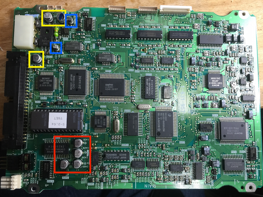

All models are expected to fail in the same way. Note that there are differences in the onboard ROM. The DEC, Apple SC Plus, and NeXT drives are hardware compatible, and the ROMs can be swapped between drives. The AppleCD 150 is not ROM compatible, but the hardware is visually almost identical. ROM Replacement part: NM27C256Q-150

The proper NeXT ROM will remove the "MESSAGE REJECT RECEIVED" error messages at system boot. The messages can safely be ignored with no affect on functionality, but are not present in the NeXT implementation.

DEC ROM Example:
DEC ROM Example

NeXT ROM Example:
NeXT ROM Example

Capacitor Replacement

Step 1)
Open the silver side of the CDROM. Remove the 2 screws in the back. Then remove the sliver cover. This will expose the logic board.
CDU-541  SONY SCSI CDROM

Step 2)
Disconnect the cables on the side of the drive. Be -very- careful with the brown ribbon connector. This part is extremely fragile and if you rip the cable you're likely going to have to scrap the drive. Use a small screwdriver to lift up and release the assembly.

cables


Step 3)
Remove the logic board by removing the front 2 screws. Then gently lift out and disconnect the 2 remaining cables.

Remove additional Cables


Step 4)
Replace the capacitors. I use ceramic capacitors to replace the electorlytics so that I don't have to worry about leaking caps in the future.

You will need:
Capacitance
Voltage
Tolerance
Temp
Dimensions
Part #
Quantity
Locations
Notes
10uF
16V
20%
125C
1206
GRM31CR71C106KA12L
2
Blue
Ceramic Replacement Part
47uF
16V
20%
85C
1206
C3216X5R1C476M160AB
3
Yellow
Ceramic Replacement Part
100uF
6.3V
20%
85C
1206
C3216X5R0J107M160AB 4
Red
Ceramic Replacement Part


Total
9


logix board


Example with ceramic capacitors installed:
new caps installed

Optional:


Replace the capacitors on the front panel. I saw no problems with these caps, but if you want to be complete, remove the front panel.
audio

Capacitance Voltage
Tolerance
Temp
Dimensions
Part #
Quantity
Locations
Notes
100uF
6.3V
20%
105C


3


1uF
50V
20%
105C


1


Total
4


Before re-assembling I recommend cleaning the laser lens as well. Take a cotton swap and high grade alchohol and gently clean.

laser assembly