MegaPixel LCD Project
Welcome hackaday! If you are interested in more NeXT stuff please join us here: http://www.nextcomputers.org/forums/index.php
Bare sound boards can be purchased from Rob at blackhole computers for $25.
Background:
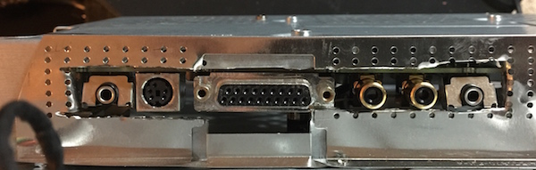
The original NeXT MegaPixel monitor gets power, video, and I/O from a
single 19 pin cable. There is a control board (known as the sound
board) inside which is identical to what is found in a NeXT soundbox.
Having a spare soundbox board I decided to embed it into a 19" LCD
monitor. In a previous hack I have shown that you can convert a new ADB soundboard to be compatible with non-ADB peripherals. I recommend you at least read that article before proceeding so you'll have a basic familiarity with the device.
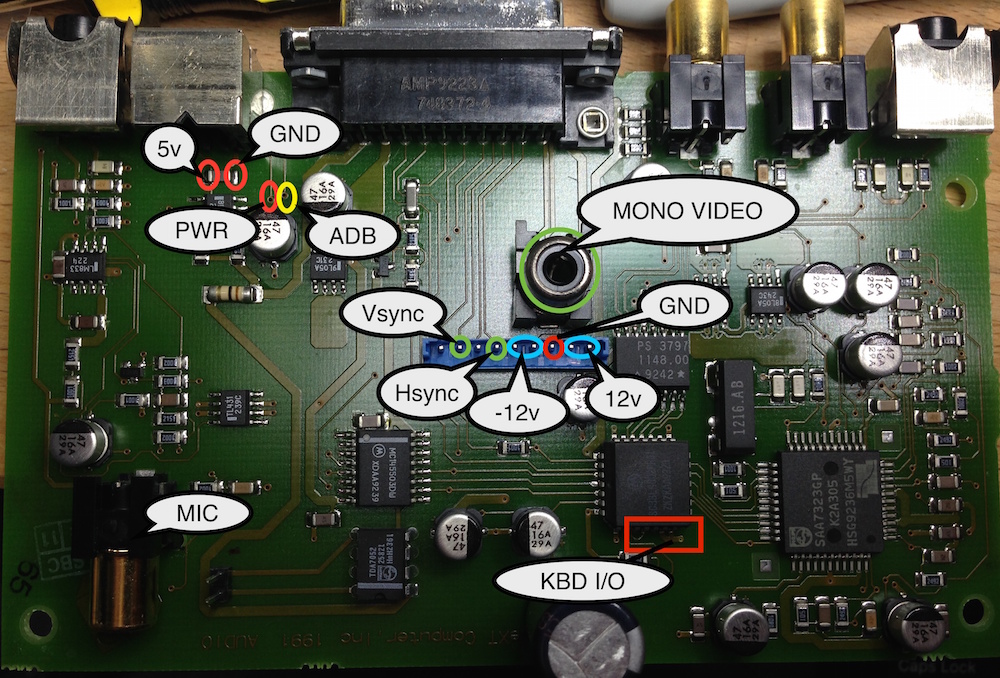
ADB Sound Board Layout:
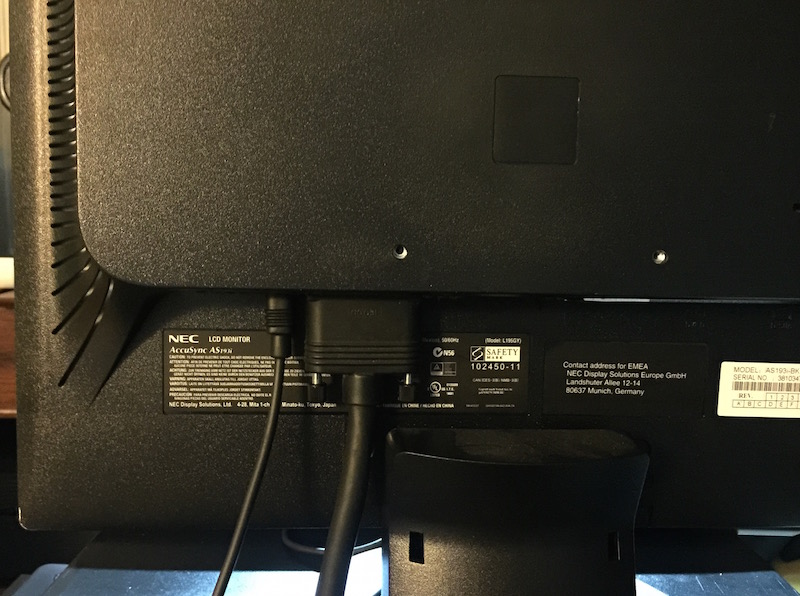
Step 1) Monitor selection
The monitor you choose will need to support Sync on
Green (SoG) as well as 1120 x 832 x 68 hz resolution. This is non
standard so usually the monitor will do some form of scaling. NEC
multisyncs are usually a good bet. I have used an NEC AccuSync AS193i
for this mod. The other criteria which will be harder to qualify
without opening the device is that it should opperate internally at
12V. All steps below are specific to the accusync, but you should be
able to adapt these to any monitor.
Step 2) Crack open the monitor
Start by removing the base. Then pry off the bezel.
I gently used a screw driver and worked my way around. There are no
screws attaching the front bezel, only plastic clips. The LCD assembly
should now lift out from the plastic back. Remove the screw from around
the LCD and lift up slowly. Disconnect the video and backlight cables.
Step 3) Remove the power supply
The power supply is the biggest component in the
case. It also provides the perfect replacement footprint for the sound
board. The board is actually designed to output 12.5V but we will be
using the ~12 output from the soundboard. This is OK, we just won't see
the maximum brightness from the monitor. There are also 2 control wires
that are routed through this board. We will need to directly connect
those wires. Further we need to generate a 5V supply for the logic
board.

Step 4) Cut your holes
Basically just cut a hole in the case for you external connections. A dremmel is your friend here.
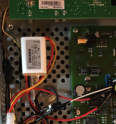
Step 5) Generate 5V
I took the easy way out here. I just purchased a
step down converter from Amazon. It was only $5 and generates almost no
heat, so I think this is the best approach. Alternatively you could use
a regulated setup. For the amazon model, just connect 12V and GND from
the soundboard to the input and connect the output to the logic board.
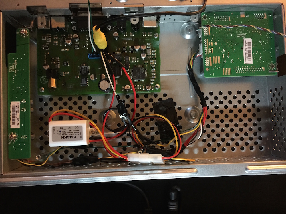
Step 6) Wire the 12V
Just connect 12V from the soundboard directly to the 12V inputs on the
inverter and logic board. I used some molex connectors to make things
modular, but that is optional if you want to solder directly.
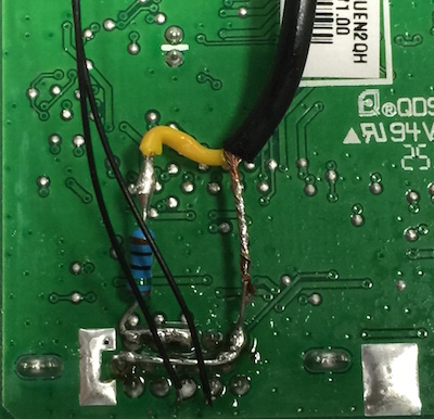
Step 7) Wire VGA
Use my last guide as a reference for the pinouts. Just solder to the back of the connector.
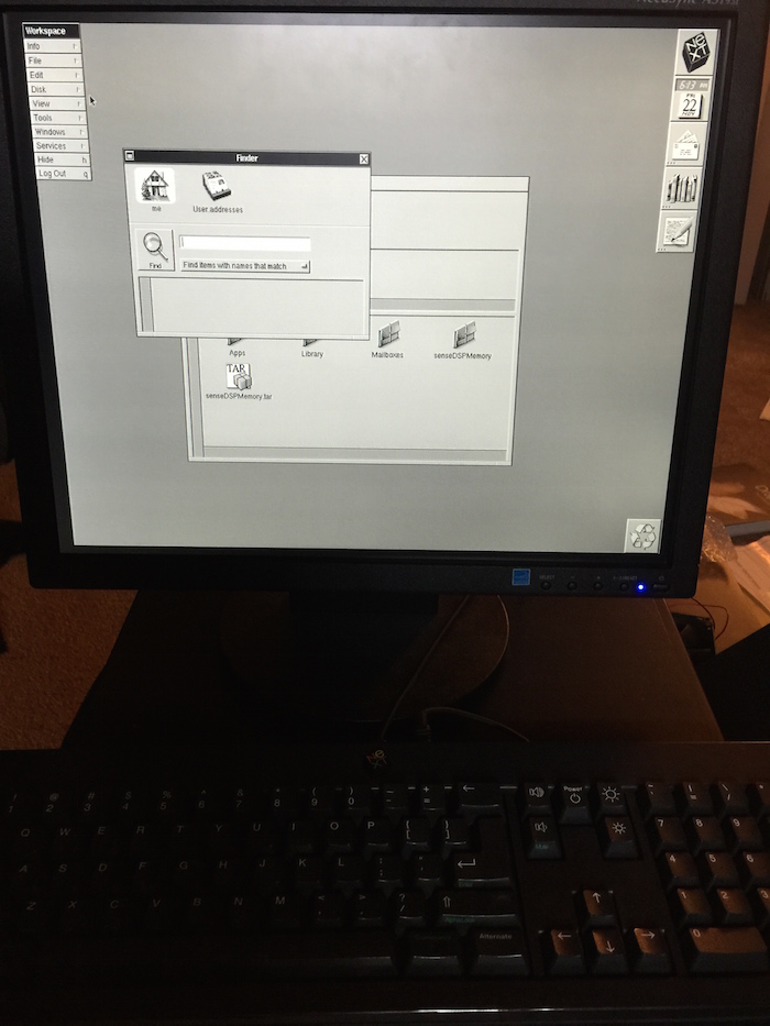
Step 8) Power it up
If all goes well you should be done. I had some
problems with grounding. Make sure that the dsub connector is properly
grounded to the chassis.